Shear Plate Settings
- General Overview
- Tips and Tricks
- Related Tools
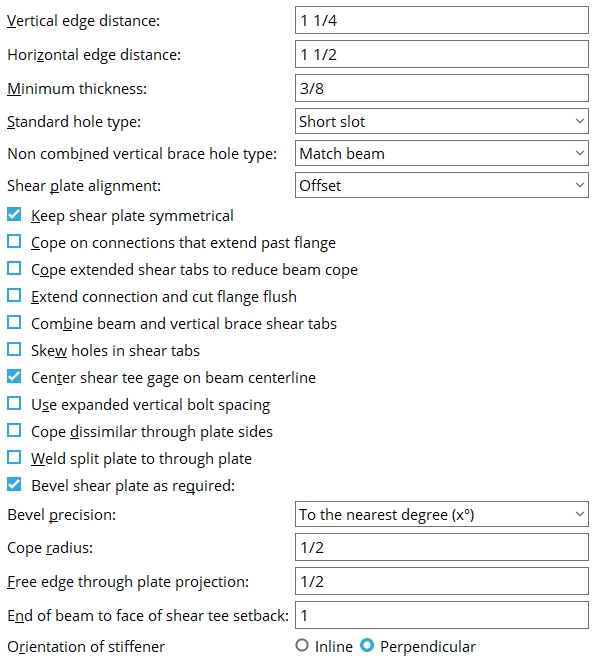
Vertical edge distance: The minimum distance from the top or bottom edge of the shear plate to the center of the nearest hole.
|
Lv = vertical edge distance. |
Effect on connection design: The vertical edge distance entered here is the minimum vertical edge distance that connection design applies to shear plates. The minimum applies to shear plates for both beams and joists. If there is a conflict between this minimum edge distance and the per diameter " Default bolt edge distance " in Bolt Design Criteria , connection design uses the larger minimum.
Horizontal edge distance: The minimum distance from the center of the nearest column of holes to the free edge of the shear plate. When " ![]() Keep shear plate symmetrical " is checked, the designed bolts-to-free-edge distance will likely be larger than the distance that is entered here.
Keep shear plate symmetrical " is checked, the designed bolts-to-free-edge distance will likely be larger than the distance that is entered here.
|
Lh = horizontal edge distance. |
Effect on connection design: The horizontal edge distance entered here is the minimum horizontal edge distance that connection design applies to shear plates. This applies to shear plates for both beams and joists. If there is a conflict between this minimum edge distance and the per diameter " Default bolt edge distance " in Bolt Design Criteria , connection design uses the larger minimum.
Minimum thickness: The minimum thickness of the plate used for moment shear plates and beam-to-beam splice plates .
Effect on connection design: When connection design creates a moment shear plate or splice plate, the plate that is used is as thick or thicker than the thickness entered here. How much thicker depends on the shear load on the connection.
Tip: To set the minimum thickness for single-plate shear connections (shear tabs) and through plates, use the Schedule of Minimums for Single-Plate Shear Connections .
Standard hole type: Standard round or Short slot or Long slot or Oversized round or User slot #1 or User slot #2 .

Effect on connection design: The hole type entered here applies to the connection design of shear plates (beams & joists). Connection design determines the specific hole size applied to shear plates per " Connection design method " specifications, based on the hole type entered here and the diameter of the bolt that is used.
Non combined vertical brace hole type: Match beam or Standard round or Short slot or Long slot or Oversized round or User slot #1 or User slot #2 . This applies when the option to " Combine beam/vbr shear plates " is set to ' No '.
|
A vertical brace to a beam and column with a non-combined shear connections on the beam and vertical brace gusset plate. |
' Match beam ' instructs connection design to create the shear plate on the gusset plate using the same " Standard hole type " that is specified for the beam.
Selecting one of the other menu choices (' Standard round ' or ' Short slot ' or ' Long slot ' or ' Oversized round ') instructs connection design to create all non-combined shear plates (except user and user defined) using that specified hole type.
Shear plate alignment: Opposite or Offset . This applies to shear plates on the same beam (or joist) when the " Shear plate/tee side " (beam) or " Shear plate side " (joist) is set to ' Automatic ' under the " ![]() Connection specifications " on the beam/joist window or at Home > Project Settings > Job > Connections > Auto Standard Connections or User Defined Connections
Connection specifications " on the beam/joist window or at Home > Project Settings > Job > Connections > Auto Standard Connections or User Defined Connections
|
||
| To get the results shown here, the " Shear plate/tee side " must be set to ' Automatic ' for both the left and right ends of a beam. For a joist (not shown), " Shear plate side " must be ' Automatic '. |
When the " Shear plate/tee side " or " Shear plate side " is ' Automatic ' (both ends) . . .
' Opposite ' designates that both the left-end and the right-end shear plates be fastened to the near side of the web of the beam (or knife plates of the joist).
' Offset ' designates that the shear plates be fastened on opposite sides of the beam's web (or knife plates of the joist). The left-end shear plate will fasten to the near side of the beam or joist. The right-end shear plate will fasten to the far side.
Keep shear plate symmetrical: ![]() or
or ![]() . This applies to shear plates for beams or joists. It does not apply to "
. This applies to shear plates for beams or joists. It does not apply to " ![]() Extend past flange " shear plate connections and may also not apply to skewed shear plate connections.
Extend past flange " shear plate connections and may also not apply to skewed shear plate connections.
|
|
If this box is checked (
), connection design centers the column of holes between the fixed edge and the free edge of the shear plate. To design a plate that is symmetrical, connection design may add extra space between the bolt column and the free edge of the shear plate, thus increasing the width of the plate.
If the box is not checked (
), connection design may create shear plates that are not symmetrical. The distance from the center of the holes to the free edge of the shear plate will likely be smaller; closer to the Horizontal edge distance ."
Cope on connections that extend past flange: ![]() or
or ![]() . This applies to perpendicular beam-to-beam shear plate connections when the " Extend past flange " box is checked.
. This applies to perpendicular beam-to-beam shear plate connections when the " Extend past flange " box is checked.
|
|
If this box is checked (
If the box is not checked (
Cope extended shear tabs to reduce beam cope: ![]() or
or ![]() . This applies to beam-to-beam shear plate connections when the " Extend past flange " box is not checked and ' Both flanges ' is selected for " Extend size to ."
. This applies to beam-to-beam shear plate connections when the " Extend past flange " box is not checked and ' Both flanges ' is selected for " Extend size to ."
|
|
If the box is checked (
If the box is not checked (
For a shear plate to be coped, it must stick out at least 1/2 inch past the supporting beam flanges. The supported beam's " Field clearance " or " Minus dimension " must be sufficiently large for the shear plate to stick out this much.
Extend connection and cut flange flush: ![]() or
or ![]() .
.
|
|
If this box is checked (
If the box is not checked (
Combine beam and vertical brace shear tabs: ![]() or
or ![]() . For a vertical brace to a beam and column, connection design creates a shear plate for the gusset-to-column interface if the beam connects to the column with a shear plate. This field lets you set the default for whether or not you want the shear plates combined into a single plate. It applies when " Combine beam/vbr shear plates " is set to ' Automatic ' under the shear "
. For a vertical brace to a beam and column, connection design creates a shear plate for the gusset-to-column interface if the beam connects to the column with a shear plate. This field lets you set the default for whether or not you want the shear plates combined into a single plate. It applies when " Combine beam/vbr shear plates " is set to ' Automatic ' under the shear " ![]() Connection specifications " on the Beam Edit window or at Home > Project Settings > Job > Auto Standard Connections or User Defined Connections .
Connection specifications " on the Beam Edit window or at Home > Project Settings > Job > Auto Standard Connections or User Defined Connections .
|
|
When " Combine beam/vbr shear plates " is ' Automatic ' . . .
If this box is checked (
If the box is not checked (
Skew holes in shear tabs:
![]() or
or ![]() . This applies to shear plates on slightly sloping beams or joists. For beams, the box also needs to be checked at Home > Project Settings > Fabricator > Detailing > Member Detailing Settings > the " Beams " section > "
. This applies to shear plates on slightly sloping beams or joists. For beams, the box also needs to be checked at Home > Project Settings > Fabricator > Detailing > Member Detailing Settings > the " Beams " section > " ![]() Square cut ends of sloped beams ." It applies when " Skew holes in plate (beam) " or " Skew holes in plate (joist) " is set to ' Automatic ' under "
Square cut ends of sloped beams ." It applies when " Skew holes in plate (beam) " or " Skew holes in plate (joist) " is set to ' Automatic ' under " ![]() Connection specifications " on the beam/joist window or at Home > Project Settings > Job > Auto Standard Connections or User Defined Connections .
Connection specifications " on the beam/joist window or at Home > Project Settings > Job > Auto Standard Connections or User Defined Connections .
|
|
When " Skew holes in plate (beam) " or " Skew holes in plate (joist) " is ' Automatic ' . . .
If this box is checked (
If the box is not checked (
Center shear tee on beam centerline: ![]() or
or ![]() . This applies to shear connections with " W Tee " selected as the " Material type " and ' Bolted ' selected for " Attachment ."
. This applies to shear connections with " W Tee " selected as the " Material type " and ' Bolted ' selected for " Attachment ."
|
|
If this box is checked (
If the box is not checked (
Use expanded vertical bolt spacing: ![]() or
or ![]() . This can apply to a ' Non-moment ' shear plate or shear tee connection. It applies when ' Automatic ' is the choice made to " Use expanded vertical bolt spacing " (beam) under the
. This can apply to a ' Non-moment ' shear plate or shear tee connection. It applies when ' Automatic ' is the choice made to " Use expanded vertical bolt spacing " (beam) under the ![]() Connection specifications "
Connection specifications "
|
|

When " Use expanded vertical bolt spacing " is ' Automatic ' . . .
If this box is checked (
If this box is not checked (
Tip: Expanded vertical hole spacing can help to reduce fabrication costs by minimizing the number of rows of bolts in shear plates and shear tees.
Cope dissimilar through plate sides: This applies to shared shear through plates with sides of unequal depth.
|
|
If this box is checked (
If this box is not checked (
Related options on this screen: " Cope radius " and " Free edge through plate projection ."
Weld split plate to through plate: ![]() or
or ![]() .This applies when " Weld split plate to through plate " is set to ' Automatic ' under "
.This applies when " Weld split plate to through plate " is set to ' Automatic ' under " ![]() Connection specifications " on the Beam Edit window or at Home > Project Settings > Job > Auto Standard Connections or User Defined Connections .
Connection specifications " on the Beam Edit window or at Home > Project Settings > Job > Auto Standard Connections or User Defined Connections .
|
|
When " Weld split plate to through plate " is ' Automatic ' . . .
If this box is checked (
If this box is not checked (
Bevel shear plate as required: ![]() or
or ![]() . This applies when " Bevel shear plate as required " (beam) or " Bevel shear plate as required " (joist) is set to ' Automatic ' under "
. This applies when " Bevel shear plate as required " (beam) or " Bevel shear plate as required " (joist) is set to ' Automatic ' under " ![]() Connection specifications " on the beam/joist window or at Home > Project Settings > Job > Auto Standard Connections or User Defined Connections . This applies to beams or joists framing skewed to beams or to columns.
Connection specifications " on the beam/joist window or at Home > Project Settings > Job > Auto Standard Connections or User Defined Connections . This applies to beams or joists framing skewed to beams or to columns.
|

When " Bevel shear plate as required " or " Bevel shear plate as required " is ' Automatic ' . . .
If this box is checked (
If this box is not checked (
Bevel precision: 0 or 1 or 2 or 3 or 4 . This sets the decimal precision (places after the decimal point) to which a shear plate will be beveled when " Bevel shear plate as required " (beam) or " Bevel shear plate as required " (joist) in ![]() Connection specifications "
Connection specifications "
' 0 ' bevels the shear plate to the nearest degree ( x ° ).
' 1 ' bevels the shear plate to the nearest tenth of a degree ( x.x ° ).
' 2 ' bevels the shear plate to the nearest hundredth of a degree ( x.xx ° ).
' 3 ' bevels the shear plate to the nearest thousandth of a degree ( x.xxx ° )..
' 4 ' bevels the shear plate to the nearest ten-thousandth of a degree ( x.xxxx ° ).
Cope radius: A distance in the primary dimension " Units " or other units . This applies when a shared through plate has been coped due to the option " ![]() Cope dissimilar through plate sides " being checked.
Cope dissimilar through plate sides " being checked.
|
Vertical and horizontal construction lines at the vertex points ( vtpt ) of the cope meet at the center point of a construction circle whose " Radius " is equal to the " Cope radius ." |
Free edge through plate projection: The distance that the through plate projects past the outside HSS wall on the free-edge side of a single-sided through plate. As shown the bottom example, this projection also applies when a shared through plate has been coped . The projection is needed to accommodate weld.
|
p = free edge through plate projection. In this example, the projection is for the free-edge side of a single-sided through plate. |
|
In this example, the " Free edge through plate projection " positions where the cope begins on the coped side of a shared through plate. |
End of beam to face of shear tee setback: The distance that the end of the beam is to be set back from the face of the shear tee connection.
|
s = end of beam to face of shear tee setback. |
A related setting: " Shear tees " ( Field Clearances ).
Orientation of stiffener: Inline or Perpendicular . This applies when the box is checked for " ![]() Stiffener opposite " (joist) or
Stiffener opposite " (joist) or ![]() Stiffener opposite "
Stiffener opposite "![]() Connection specifications " for a joist or beam with a shear plate connection that is framed skewed to a supporting beam. Also in connection specifications, something other than
Connection specifications " for a joist or beam with a shear plate connection that is framed skewed to a supporting beam. Also in connection specifications, something other than
|
||||||
| The above screen shots were taken from beneath the top flange of the supporting beam. Since the joist flush frames to the beam, the view of the joist is also beneath its top of steel. |
'
Inline ' aligns the stiffener at the same skew as the shear plate.
'
Note: If the supported beam or joist is perpendicular to the supported beam, then either choice (inline or perpendicular) will produce the same results.


|
|
OK (or the Enter key) closes this screen and applies the settings.
Cancel (or the Esc key) closes this screen without saving any changes.
Reset undoes all changes made to this screen since you first opened it. The screen remains open.
-
Settings applied here are for your current Fabricator . Each Fabricator in your current Job is a different collection of settings. This allows you to change to a different set of Standard Fabricator Connections each time you " Change Fabricator."
- These settings work in coordination with individual beam shear plates "
 Connection specifications " and shear plate configurations to configure connection design for when the Beam Edit window > " Connection type " > " Input connection type " is ' Shear plate ' or ' Auto standard ' or ' User defined '. Many options on this screen also work in coordination with connection specifications for flush framed joist shear plate connections.
- Shear input specs (settings for defining shear connections)
- Setup for shear connections (index)
- Connection guide (examples of shear connections)

